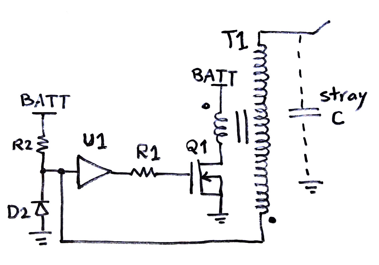

Due to it’s size, the resonant capacitor is mounted separately. To shrink the size and height of electronics (which is important due to proximity to high voltage output), surface mount components were used. Pulse duration and repetition rate is also limited by frequency characteristic of the coil, which due to losses in iron limits the frequency to lower kHz range and pulse duration to minimum of about a hundred microseconds.Ī decision was made to put the whole circuit onto a single printed circuit board that is mounted compactly onto the ignition coil itself. The same occurs if the output is rectified and used for capacitor charging. This DC component may cause the primary current to integrate into unsafe values over a period of multiple cycles, unless enough time is left between the pulses for the DC component to dissipate on primary resistance and secondary voltage drop. When the secondary is loaded with an arc, it is effectively short circuited, causing a DC voltage component across the winding, which is then reflected to the primary. Such arrangement only allows operation at constant duty cycle regardless of the output load. In this particular circuit, an IRFP450 MOSFET is driven by a NE555 timer IC, with frequency and duty cycle programmable by trimmer resistors. If there is no current drawn from the output, the snubber capacitor allows recycling of the stored energy back to the power supply. If mechanical switch is replaced by a silicon one, such as a MOSFET, snubber is still required otherwise the voltage would again rise very quickly over the switch breakdown rating and energy would be lost as heat. This snubber action of the capacitor is an important feat in power electronics. Placing a capacitor across the contacts increases the output dramatically – the capacitor slows down the rate of current drop and slowing the voltage rise, allowing enough time for the contact to open without arcing over.

A careful experimenter will notice that if the switch was used alone, it will produce relatively poor output on the ignition coil and relatively large arc in the contacts. In a typical automotive applications, older type ignition coils (like used in this project) were usually triggered by a mechanical contact which opened in the moment of ignition.

An important difference is in the core material – flyback transformers use ferrite cores, and are capable of operation at much greater frequencies and power densities than ignition coils, which use iron laminations. Both ignition coils and flyback transformers have an air gap in their magnetic path, which is essential for storing energy during the on-pulse which is then released after turn-off. This allows for much higher output voltages than those available with ordinary transformers. After the current that has developed in the primary is abruptly interrupted, inductive action of the primary creates a large voltage spike which is reflected to the secondary, multiplied by the turn ratio of secondary and primary coil. Much like HV flyback transformers in cathode ray tube screens, they are driven by voltage pulses provided from a DC power supply which is interrupted by a single switch. Ignition coils are a kind of high voltage flyback transformers used in automobile ignition systems. This simple circuit is one among commonly used ignition coil drivers.


 0 kommentar(er)
